TF-Luna Security System
Hello and welcome! The second project I worked on for Blueprint was a continuation of my Arduino Security System: the TF-Luna Security System.
The natural evolution of the Arduino Security System was to design a custom PCB, create an enclosure, and make the project completely standalone and easy to use. After some initial brainstorming, I realized that this project would have to work differently and use different sensors than the original Arduino Security System. This was the core idea I built the project around:
It would use a TF-Luna LiDAR sensor to detect when someone passed through my bedroom door, which would then trigger an ESP32-CAM to take a picture. This image, along with the detection information, would then be displayed on a dashboard hosted on the ESP32 and accessible over Wi-Fi.
I already had a good idea of the process because I had followed similar steps while building Odin’s Eye. Nevertheless, I still had challenges and setbacks. For a full, detailed breakdown of the project and everything that led to it, refer to the Blueprint journal. You can also find all the project files, including the PCB designs, firmware, 3D case files, demos, and more, on GitHub.
Security System Blueprint: TF-Luna Security System Blueprint
Security System Github: TF-Luna Security System Github
In this journal, I want to give a brief overview of the TF-Luna Security System and explain what I learned while building it.
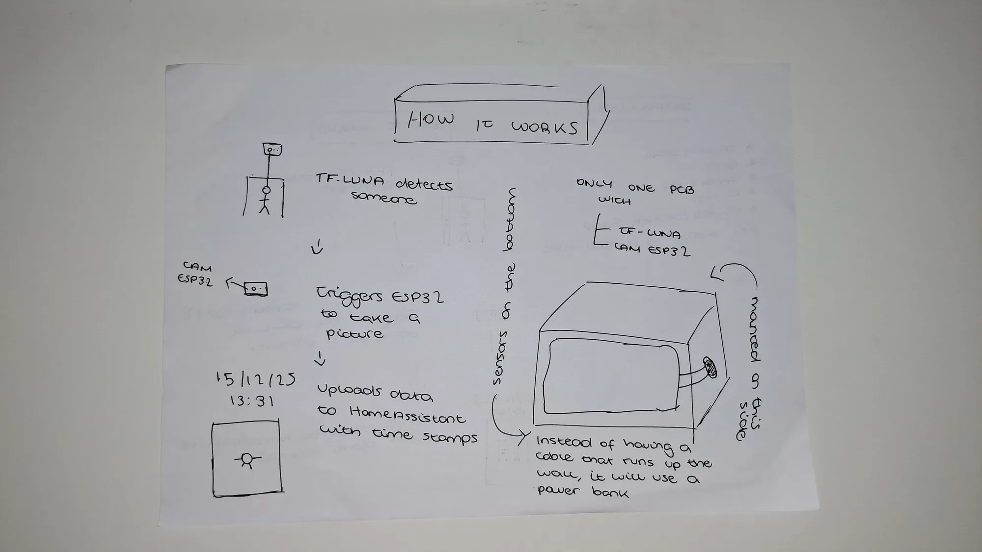
The first step was to do some research and choose the sensors and components that the system would use. I decided that the laser and laser receiver from the Arduino Security System would be difficult to implement and would require two separate PCBs, so I settled on using a TF-Luna LiDAR sensor instead. At this stage, I also made some rough sketches of how I wanted the system to function.
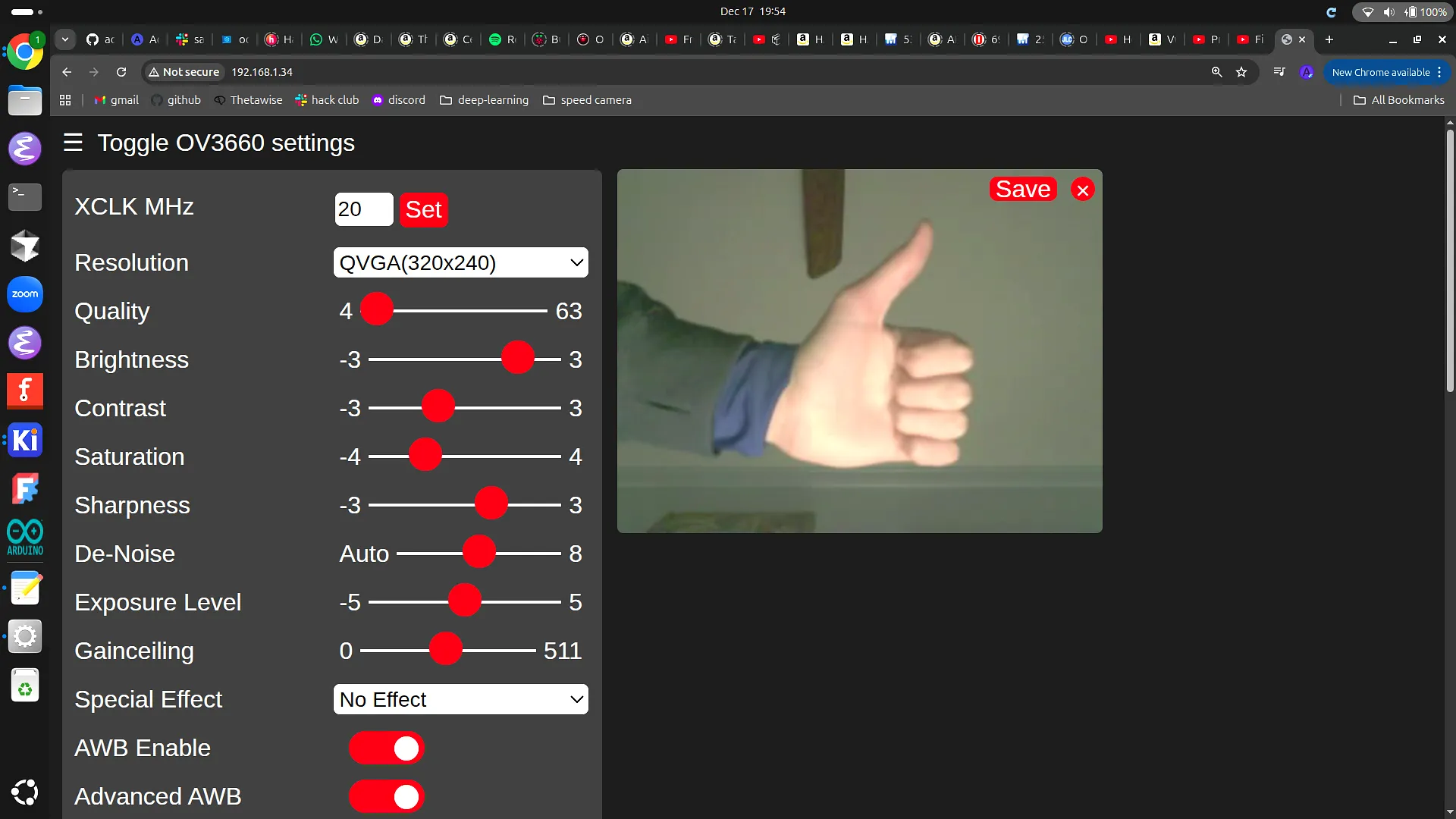
I decided to use an ESP32-S3-WROOM-1 as the main microcontroller for the project and to handle the image capture. Since I already had one available, I put together a quick proof of concept (POC) to see if the image quality would be good enough. Using the CameraWebServer example included with the Arduino IDE, I eventually got the web server up and running after a bit of trial and error.
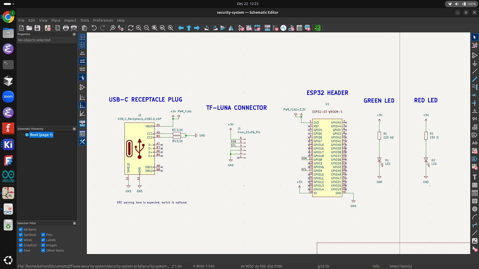
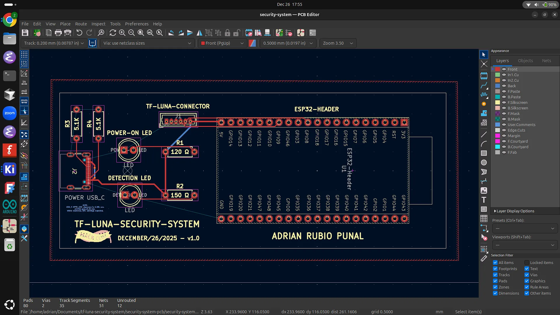
Once I had a clear idea of the parts I was going to use, I began work on the schematic for the PCB. I added all the symbols, including the TF-Luna connector, USB-C receptacle, LEDs, resistors, and even designed a custom 40-pin header for the ESP32-S3-WROOM-1. Then, I wired all the symbols together by referencing the pinouts and datasheets of the different components to ensure everything was connected correctly.
I then ran an ERC to verify that there were no issues in the schematic. It reported three errors, which I fixed by adding power flags.
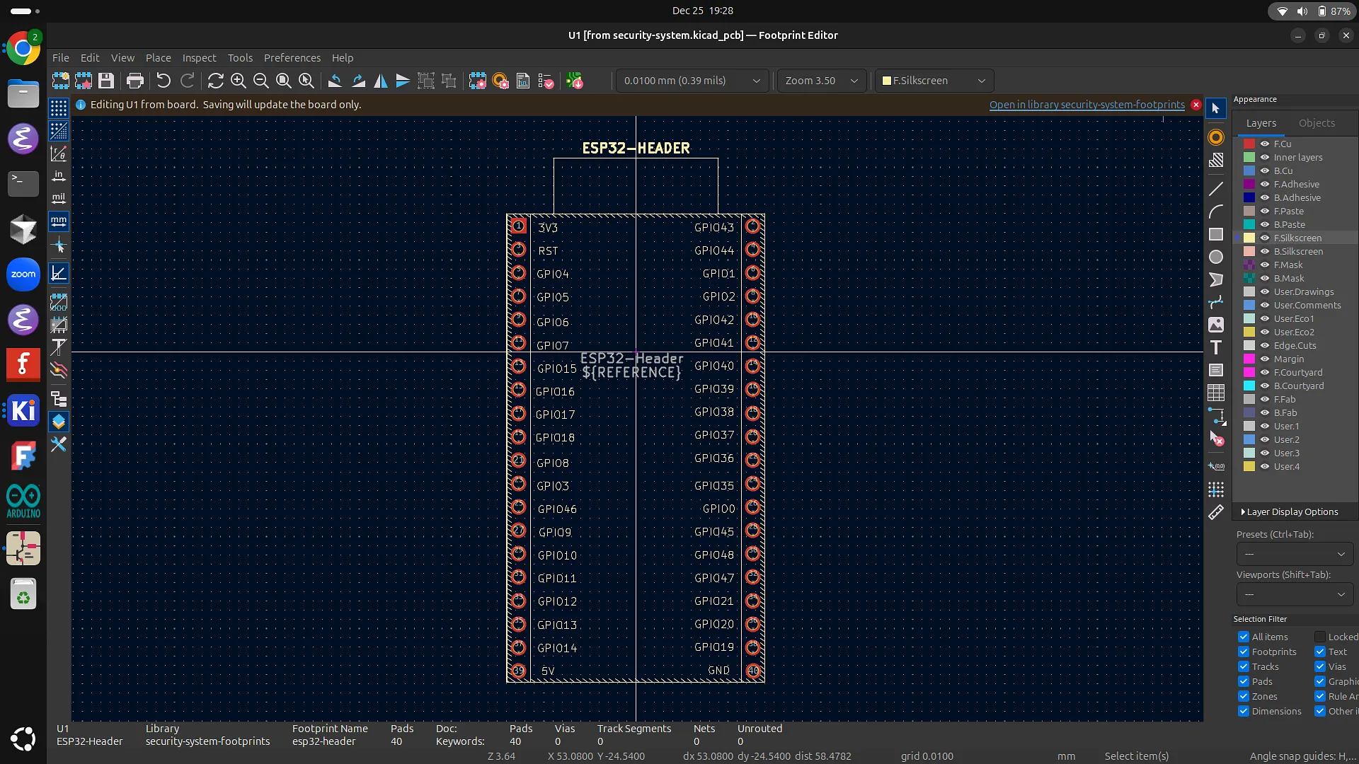
With the ERC errors resolved, I moved on to assigning footprints to each component. I did this by finding the parts on Mouser and assigning the corresponding footprints in KiCad. Most of the footprints were fairly straightforward to assign, but since there was no specific header footprint available for the ESP32-S3, I decided to design my own.
Unfortunately, after searching all over the internet for a mechanical datasheet for the FREENOVE WROOM-1 and finding nothing, I decided to contact the Freenove support team and ask for an official version. Sure enough, they got back to me with a file containing all the measurements I needed. Using this information, I was able to create an accurate footprint for the header.
At this point, I started working on the PCB design. I imported the JLCPCB board settings and created an efficient layout for the components, placing most of them on the left side of the board and the ESP32 on the right. After adding the board outline, I routed the PCB traces, which went smoothly. To finish the PCB, I added footprint labels along with a title, date, my name, and two Hack Club logos.
To verify the PCB design, I ran a DRC. Most of the violations were fixed by changing the text size of the ESP32 header, while the remaining issues were resolved by making four of the USB-C pad connections solid instead of using thermal reliefs.
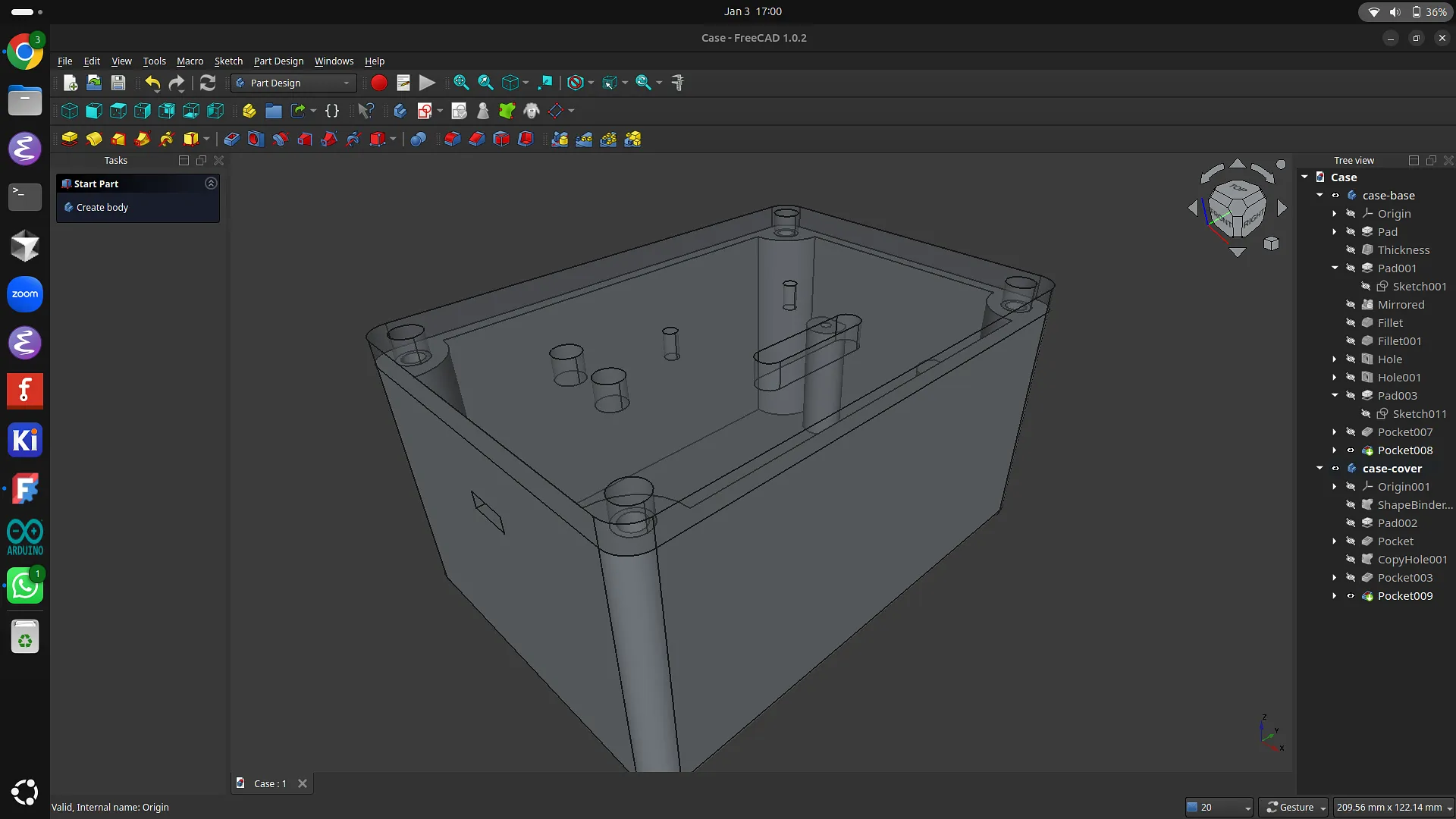
The only part of the security system left to design at this point was the 3D-printed case, so I got started on it. The basic shape of the case was similar to the one I designed for Odin’s Eye, including the four holes used to screw the cover onto the base.
I needed the PCB to be mounted on the base of the case so that the camera, LEDs, and TF-Luna sensor could align with the openings on the cover. The original cutout was too low, so I first padded the base after calculating the height required for the PCB so the LEDs and camera could properly reach the cover. Later on, I added four support pillars inside the case to keep the case stable without wasting too much filament.
Next, I created the cover, adding cutouts for the two LEDs and the TF-Luna sensor. After contacting the Freenove support team for the camera dimensions and its exact position on the board, I also added a cutout for the ESP32 camera. Finally, to complete the 3D case, I added the USB-C cutout.
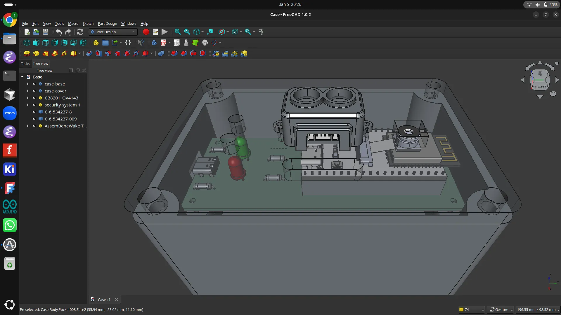
To make the 3D case as accurate as possible, I went a step further and downloaded the STEP files for each component. I then imported them into the design and positioned them inside the case. The height I had calculated for the PCB mounting pillars turned out to be perfect, as the ESP32 camera aligned correctly with the cover. However, this process also helped me identify and fix several small measurement issues, such as the camera and USB-C cutouts.
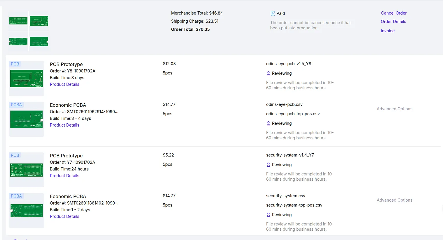
Now that I had designed, refined, and finalized the PCB and 3D case, and selected all the necessary parts, it was time to start ordering everything. I began by generating the Gerber files and uploading the BOM and CPL files to JLCPCB, where I specified that I wanted JLCPCB to assemble the SMD USB-C connector for me. After confirming that the USB-C connector was the correct component and properly positioned, I received the final quote for the PCB. Since I was already ordering PCBs from JLCPCB for Odin’s Eye, I decided to include this PCB in the same order as well.
As with Odin’s Eye, I also ordered the 3D case from a teenager in Spain through Printing Legion (a Hack Club initiative where people print parts for others and get reimbursed for filament). Finally, I ordered the remaining PCB components from Mouser.
Once everything arrived, I moved on to soldering the PCB. Since I had already started soldering Odin’s Eye before working on the security system PCB, I had developed a fairly steady hand by that point. I began with the ESP32 connectors, followed by the resistors, the TF-Luna connector, and finally the LEDs. Overall, I was really happy with how the soldering turned out.
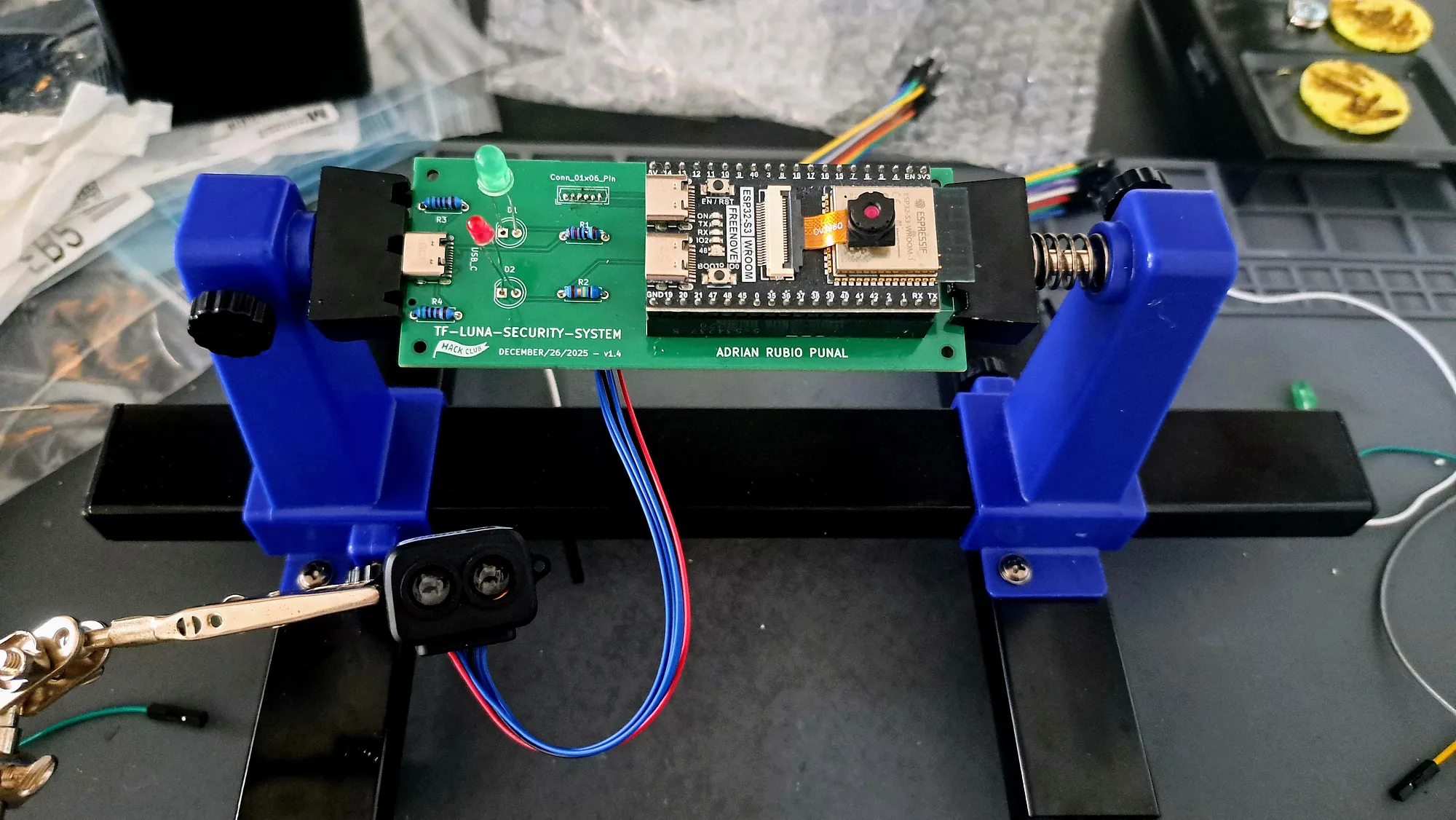
Following the PCB assembly, I made sure all the sensors were working correctly. Unfortunately, after some troubleshooting, I discovered that I had to remove the red LED’s 60-ohm resistor because it was connected to the ESP32’s GPIO 4, which caused problems with the camera. Once the camera was fixed, I created the initial version of the project code, which included a web app hosted locally by the ESP32.
While testing the web app and the detection system, I found that the TF-Luna was not working properly and was producing inaccurate distance measurements. I spent a lot of time troubleshooting the TF-Luna and trying to find the cause of the issue. After almost frying two TF-Lunas and going through multiple rounds of troubleshooting, I managed to get the project mostly functional. Eventually, I came to the conclusion that it was a hardware-related issue because the sensor could only take a few readings before the measurements became unstable, forcing me to reconnect the USB cable each time.
I modified the web app to give it a clean and polished look, and I also added a picture gallery displaying the last 100 captured images. Lastly, I completed the project by mounting everything inside the case, securing it with screws, and attaching a small power bank to the side of the case to make it completely standalone.
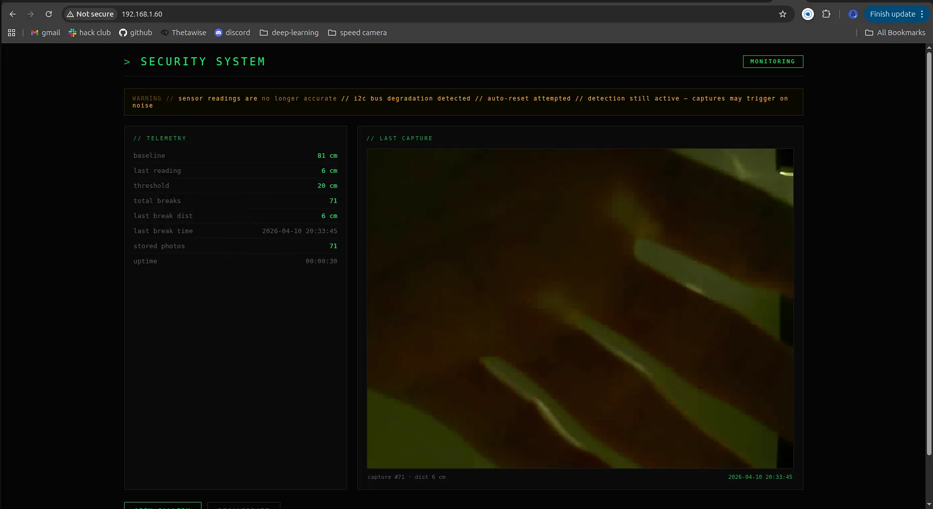
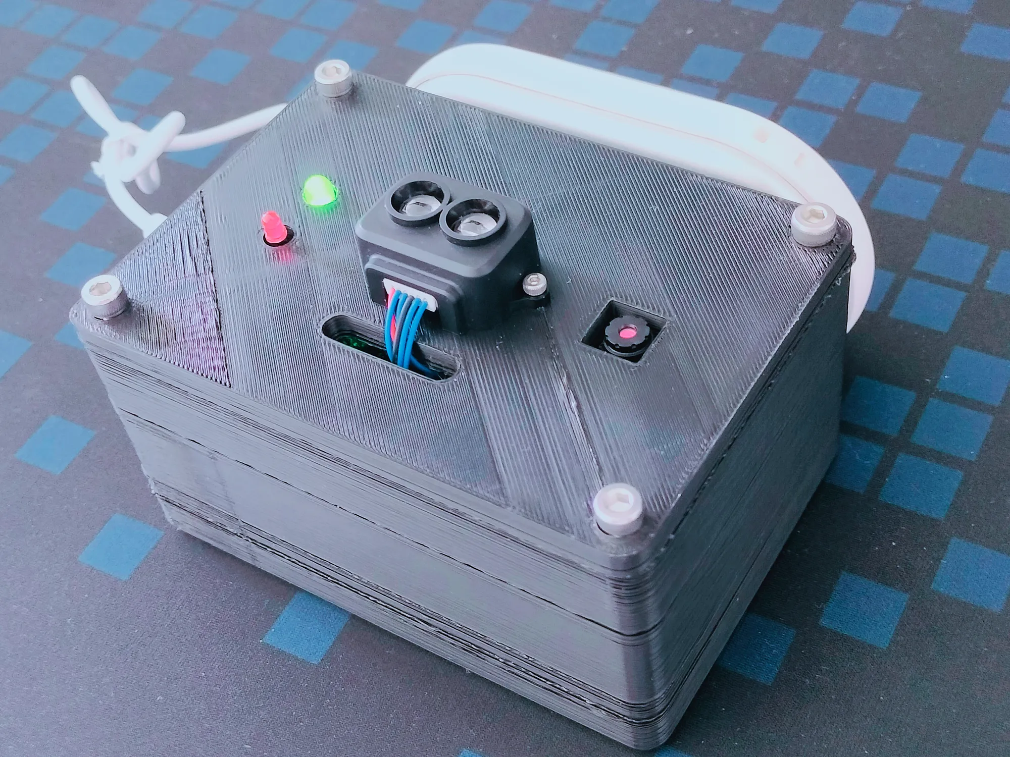
Although the project wasn’t a complete success, since I couldn’t reliably use the system due to the TF-Luna measurements becoming inaccurate over time, I still consider it a very rewarding project. I put a great deal of effort into it and significantly improved my PCB design and 3D modelling skills throughout the process. Even with the hardware issues, seeing everything finally come together into a polished final product was really incredible and made me genuinely proud of the project.
TF-Luna Security System Demo:
For a more in-depth overview of the Security System, I’d recommend checking out the Blueprint page, where I go through the full journey of the project in much greater detail.
Security System Blueprint: Security System Blueprint
I also built two smaller hardware-focused projects with the goal of earning enough tickets for a 3D printer, but along the way I ended up developing my 3D design skills far more than I originally expected.
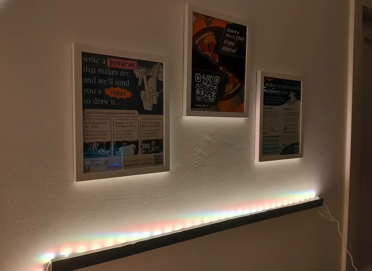
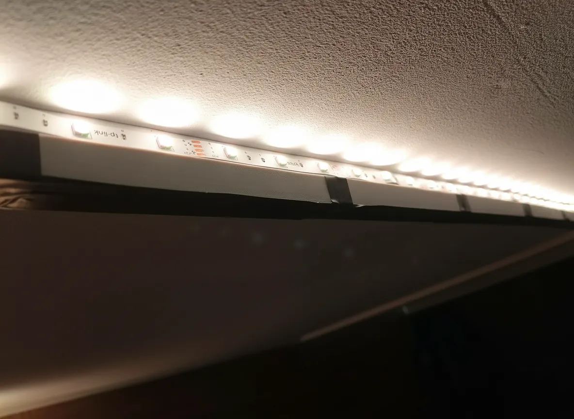
The first of these was the LED Light Bar. The goal was to design a modular 3D-printed light bar to illuminate my Hack Club posters while keeping the setup clean and practical. Although it was a relatively small project, it helped me improve my 3D design skills and gave me a better understanding of designing parts for real-world use. The finished result worked exactly as intended and looked much better than I had originally expected.
LED Light Bar Blueprint: Light Bar Blueprint
LED Light Bar Github: Light Bar Github
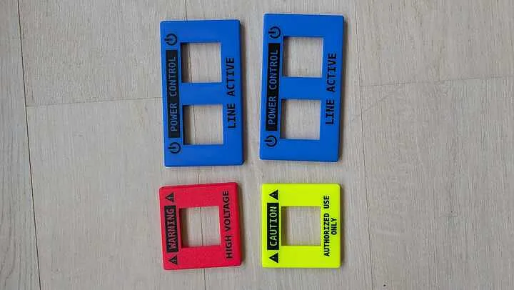
The second of these was the Light Switch Covers. For this project, I designed three custom industrial-style light switch covers for my bedroom, featuring labels such as CAUTION, WARNING, and POWER CONTROL. While working on the covers, I learned a lot more about FreeCAD, particularly when it came to creating custom text, symbols, and multi-colour designs. The final covers turned out exactly how I envisioned them and further improved my 3D design skills.
Light Switch Covers Blueprint: Light Switch Covers Blueprint
Light Switch Covers Github: Light Switch Covers Github
Blueprint has now ended, and all of my projects are currently being reviewed. Once they are accepted, I should have earned enough tickets to buy a 3D printer, which was one of my main goals when I started. Looking back, it’s amazing to see how much I managed to build and learn over the course of the program.
Blueprint has been a huge learning experience for me. I now have a solid foundation in hardware design, 3D design, soldering, and troubleshooting that I can continue building on in future projects. Many of these skills are things I do not think I could have learned nearly as well without the hands-on experience of actually designing, building, breaking, and fixing things myself. I’m very grateful for the opportunity, and I feel incredibly accomplished with what I’ve achieved. I’m excited to continue building and applying these skills to future projects.