Odin's Eye
Hello and welcome! Over the last few months, I have built four hardware projects for Blueprint which, once accepted, should earn me a 3D printer. The first of these projects was Odin’s Eye.
I introduced Odin’s Eye in the previous journal, but here’s a quick recap:
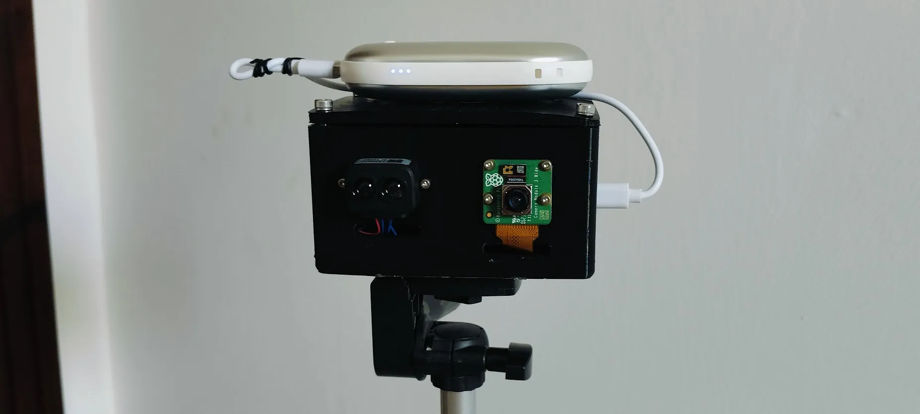
Odin’s Eye is a DIY speed camera that detects passing vehicles using a TF-Luna LiDAR sensor and measures their speed. When a vehicle passes, a Raspberry Pi Camera Module 3 takes a picture, which is then processed by a Pi Zero 2 W. Once everything is processed, the data is displayed on a dashboard that can be accessed from your phone over Wi-Fi.
After more than 40 hours of work on the project, I achieved a result that I am incredibly proud of. However, the process came with plenty of setbacks and disappointments. For a full, detailed breakdown of the project and everything that led to it, refer to the Blueprint journal. You can also find all the project files, including the PCB designs, firmware, 3D case files, demos, and more, on GitHub.
Odin’s Eye Blueprint: Odin’s Eye Blueprint
Odin’s Eye Github: Odin’s Eye Github
In this journal, I want to give a brief overview of Odin’s Eye and explain what I learned while building it.
I began the project by doing research and choosing the parts that would work best for the system. I also made some rough sketches to illustrate my initial ideas for the PCB layout, 3D case, and component placement. Looking back, most of the ideas from this stage made it into the final version of the system.
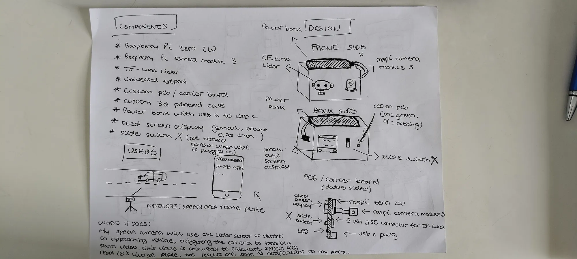
I also spent time thinking about the speed measurement method. I looked into several different approaches, including video-based tracking, Doppler radar, microwave motion sensors, and more. I eventually settled on using a TF-Luna LiDAR sensor and a least-squares fitting method to calculate vehicle speed. The LiDAR is placed at an angle facing the road and continuously takes distance readings as a vehicle passes through its field of view. Using those measurements, the system can calculate the speed of the vehicle.
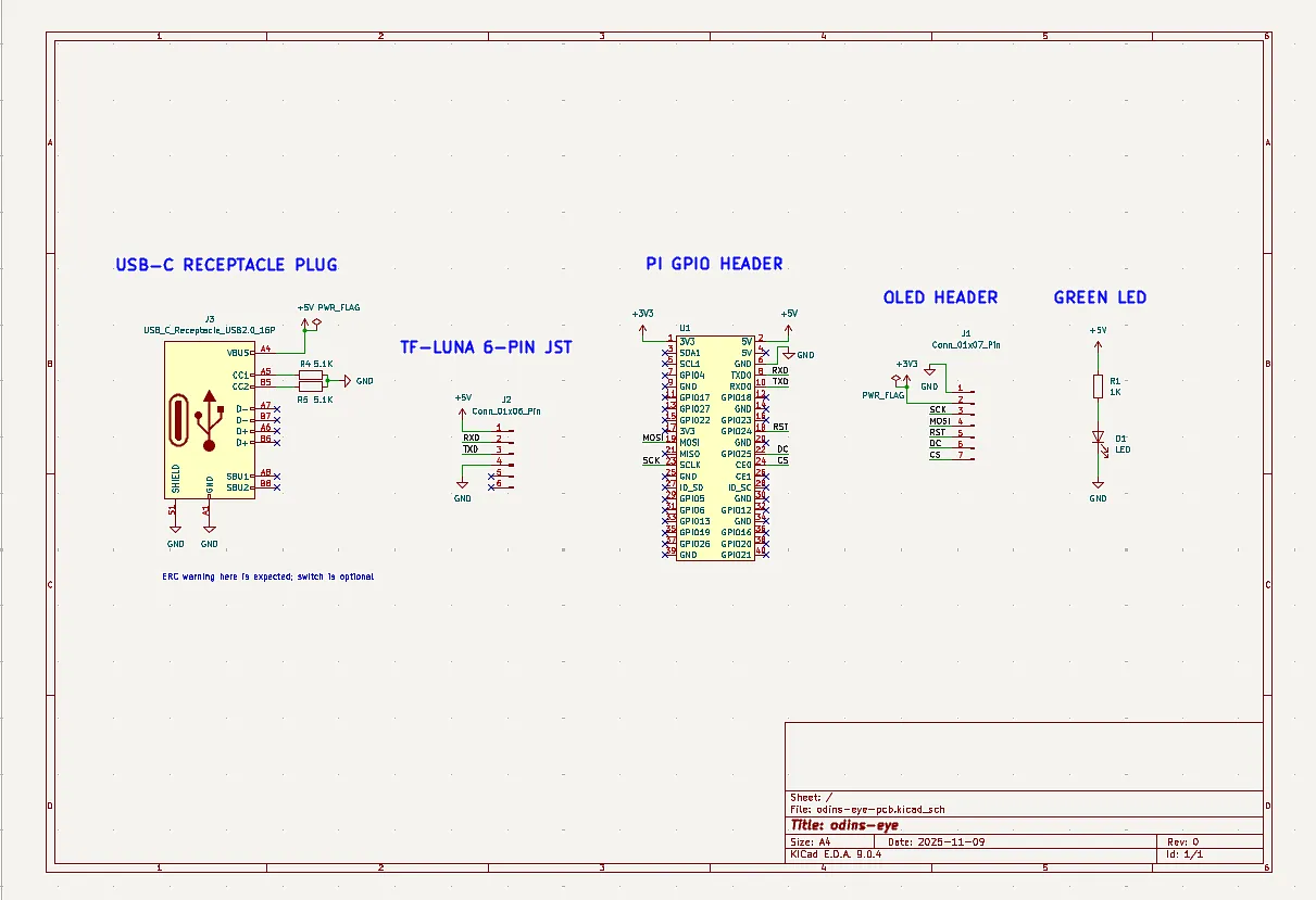
After getting a clear idea of the parts I was going to use, I felt ready to start working on the PCB design, despite it being my first time designing one. First, I installed KiCad, the software I used to design the PCB. After watching a few guides and tutorials, I felt ready to begin working on the schematic.
I added the connectors, resistors, LED, USB-C receptacle, and even designed my own header for the Raspberry Pi. I then laid out the components and connected everything by referencing the pinouts of the different parts, such as the OLED display and TF-Luna LiDAR sensor, while also checking multiple sources for the USB-C receptacle wiring.
Once I had double-checked that the schematic looked valid, I assigned footprints to each part and found matching components on either Mouser or DigiKey. All of these parts and references are documented on the Blueprint page. Most of the components were fairly easy to find, but the TF-Luna connector gave me trouble because it was not included in the sensor’s documentation. After digging through forum threads and Reddit posts, I eventually managed to narrow the options down to three possible connectors.
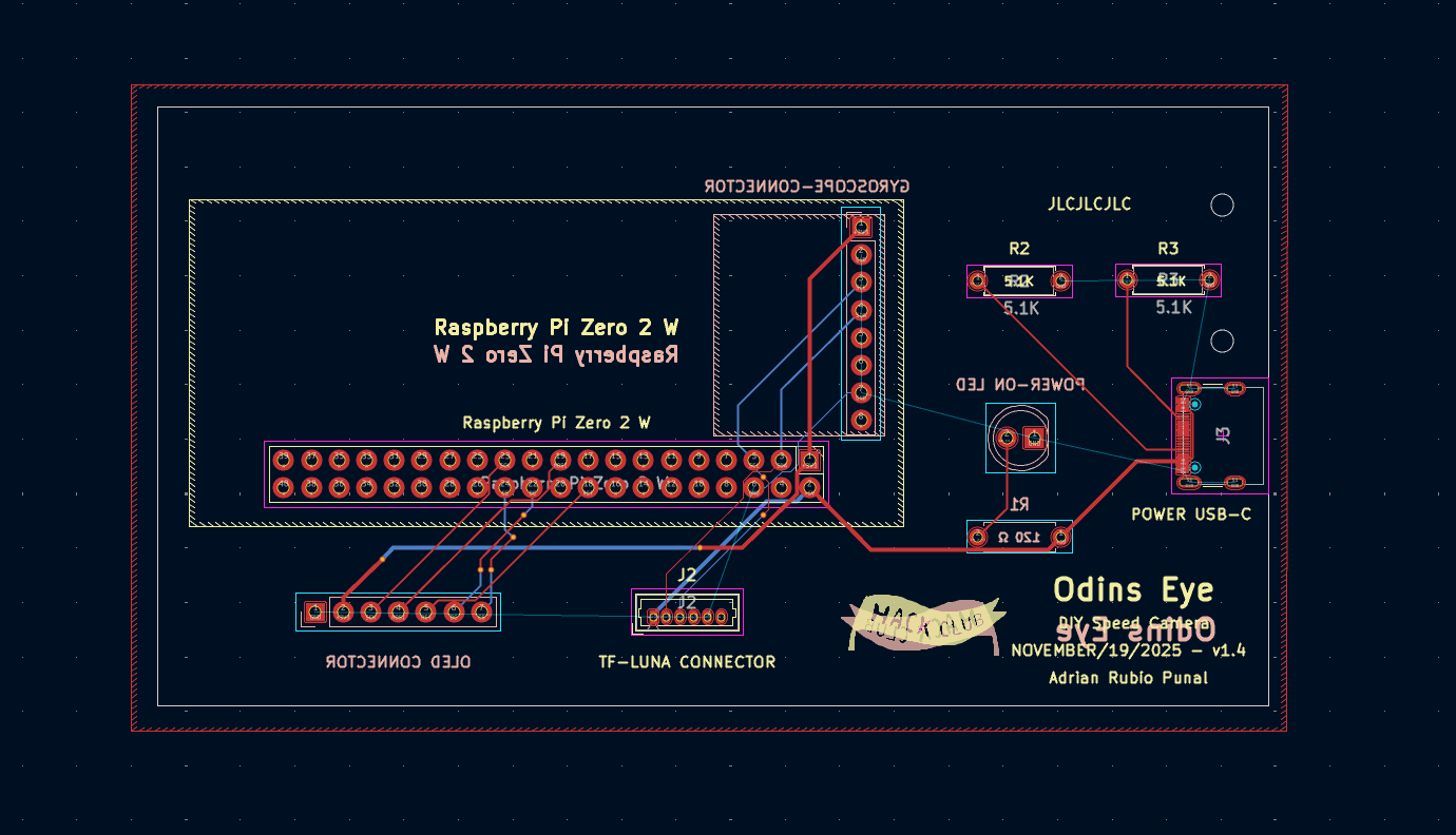
Next, I moved on to the PCB design. I imported the correct board settings and, after some trial and error, found a compact way to arrange the components, placing each footprint close to its intended position. Once I was happy with the layout, I added the board outline using the dimensions I had planned for the PCB.
Since it was also my first time designing a PCB, I watched a few tutorials and started routing the PCB traces. After fixing a few DRC violations, I improved the part labels and added some text containing the title, date, my name, and a Hack Club logo.
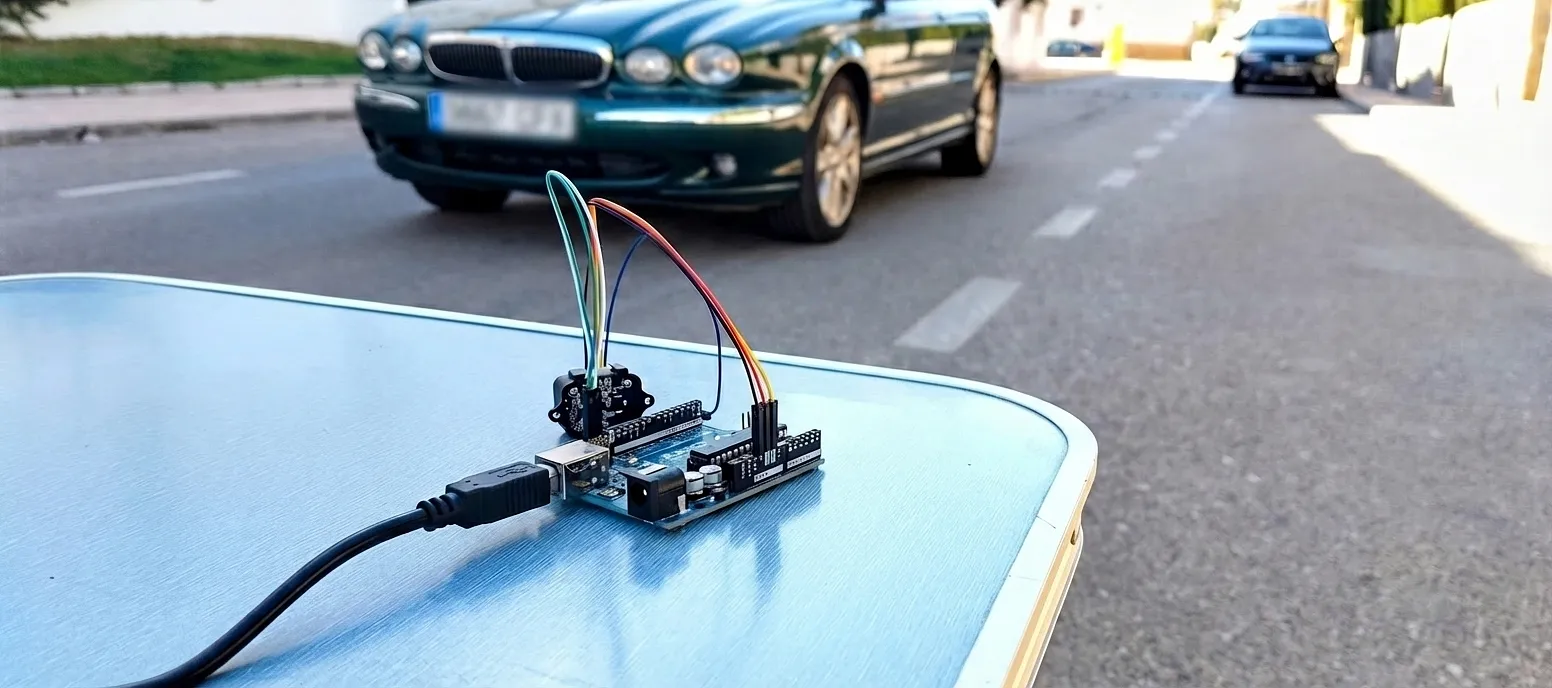
Now that the PCB was practically finished, I connected the TF-Luna that I had bought to I²C on a breadboard and created a proof of concept (POC). At first, I replicated the least-squares fit code in C++, but I wasn’t very satisfied with the results. After experimenting with different methods, I came up with an approach I called “Burst–Gap–Burst.” In simple terms, the system takes two quick groups of distance readings separated by a short pause, compares their averages, and uses the difference to calculate the vehicle’s speed.
I used the proof of concept (POC) to improve the accuracy of this new method. By the end of the testing session, the system had become surprisingly accurate. This method required the sensor to face the road at roughly a 20-degree angle to work properly. Since I wanted the project to be completely standalone, I decided to add a gyroscope to the PCB and later implement a calibration sequence in the speed camera software.
The only part of the speed camera left to design was the 3D case, so I got started on it. I installed FreeCAD and, after doing some research and experimenting with it on my own, I felt confident enough to begin designing the case.
Shortly after starting, I already had the basic shape of the case and the four holes used to screw the cover onto it. I then added a hole on the bottom of the case for a 1/4-20 heat-set insert so the system could be mounted onto a tripod. I also added a slot across the width of the base so the PCB could slide in vertically.
To give the PCB extra stability inside the case, I added a support strip on the side of the enclosure with two mounting holes, along with two matching mounting holes on the PCB itself. I also added two strips on the cover aligned with the PCB’s position inside the case.
To complete the 3D case, I added cutouts for the TF-Luna, Pi Camera, USB-C port, OLED display, and LED. I used the datasheets for each component to get the measurements I needed.
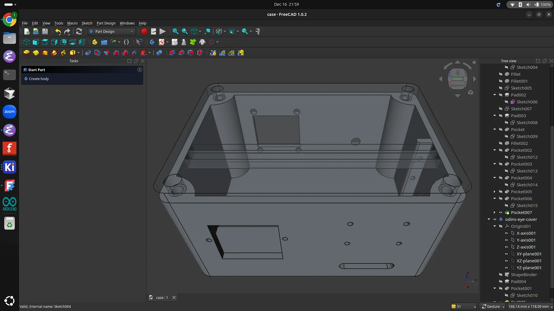
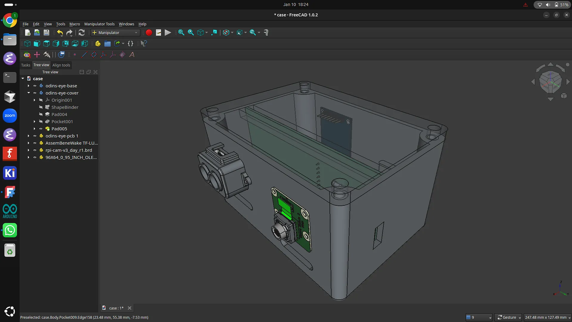
I went a step further and decided to make the 3D case as accurate as possible. To do this, I downloaded the STEP files for each component, imported them into the design, and placed them inside the case. This turned out to be an important step because it allowed me to fix several small measurement issues, such as the camera mounting holes, the LED cutout, and the USB-C cutout, that I likely would not have noticed otherwise.
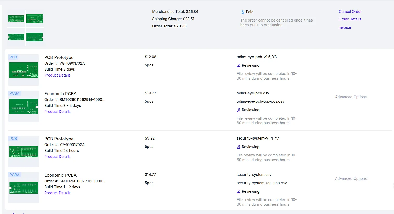
At this point, I was ready to order the PCB, components, and 3D-printed case. Since I planned to use JLCPCB as the manufacturer, I generated the Gerber files and uploaded the BOM and CPL files for assembly so they could assemble the SMD USB-C connector for me. After verifying the USB-C connector was the correct component and properly positioned, I got a quote for the PCB. It was fairly expensive because it was getting shipped from China, but I was confident that it would work, so I went ahead with the order.
I also bought the components (Pi, camera, OLED, etc.) separately, and the PCB parts from Mouser. The only thing left to order was the 3D case. I got this done by finding a teenager in Spain who had a 3D printer through Printing Legion. Printing Legion is a Hack Club initiative where people with 3D printers print parts for others who do not have access to one, then get reimbursed for the filament used.
After the PCB and parts had arrived, I began soldering. My first solder joints were noticeably worse than the later ones, by which point I had gotten the hang of it. Soldering went smoothly apart from the LED, which I had to remove after making a mistake while soldering it. Once the parts were soldered onto the PCB, I moved on to the Pi and gyroscope, and those joints turned out much cleaner.
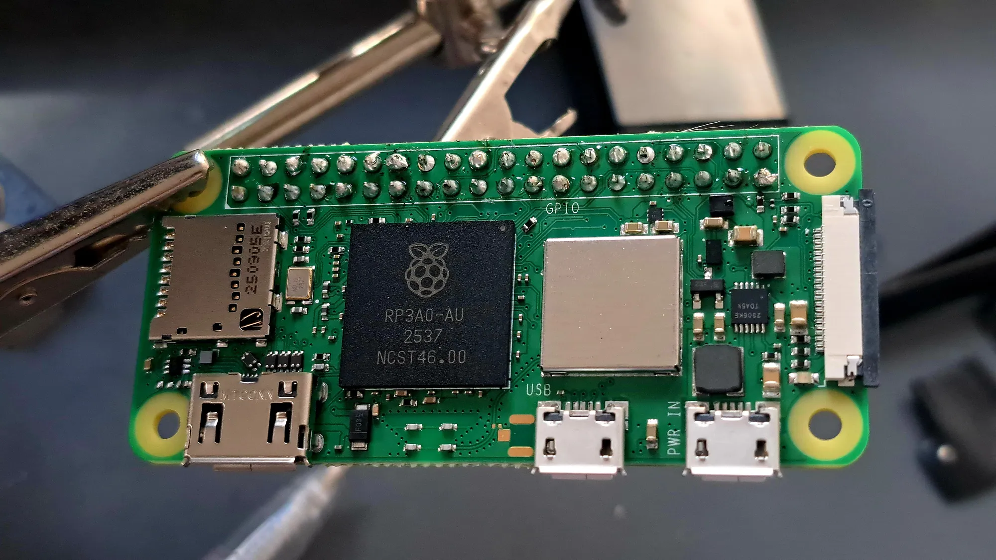
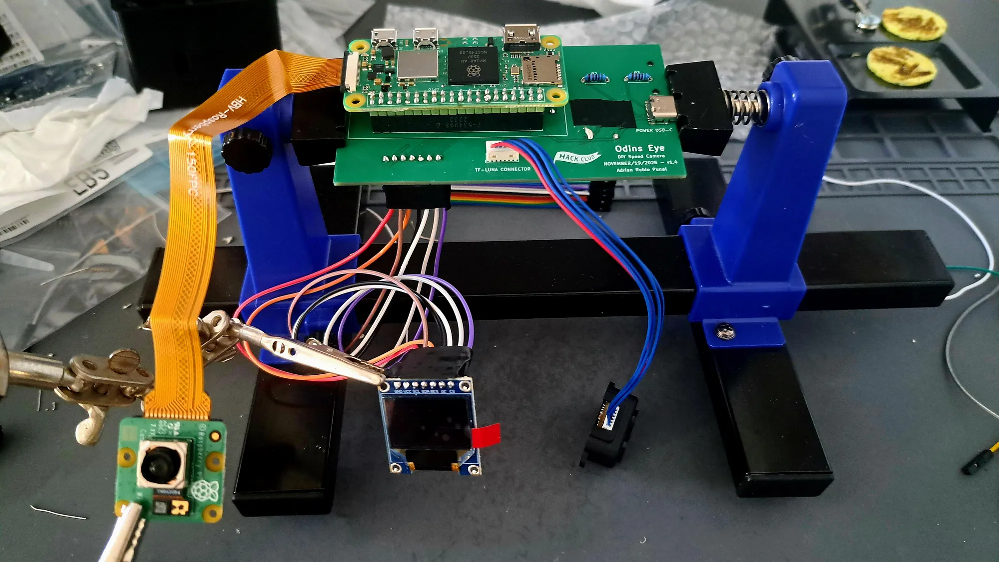
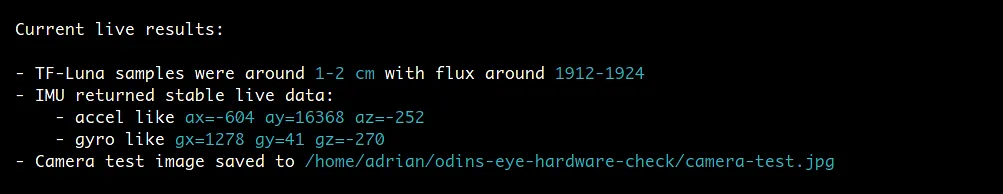
With the PCB assembled, I continued by flashing Raspberry Pi OS Lite onto the SD card I was going to use for the Pi. I then booted the Pi and got to work making sure all the sensors were recognized. All of the sensors were detected correctly.
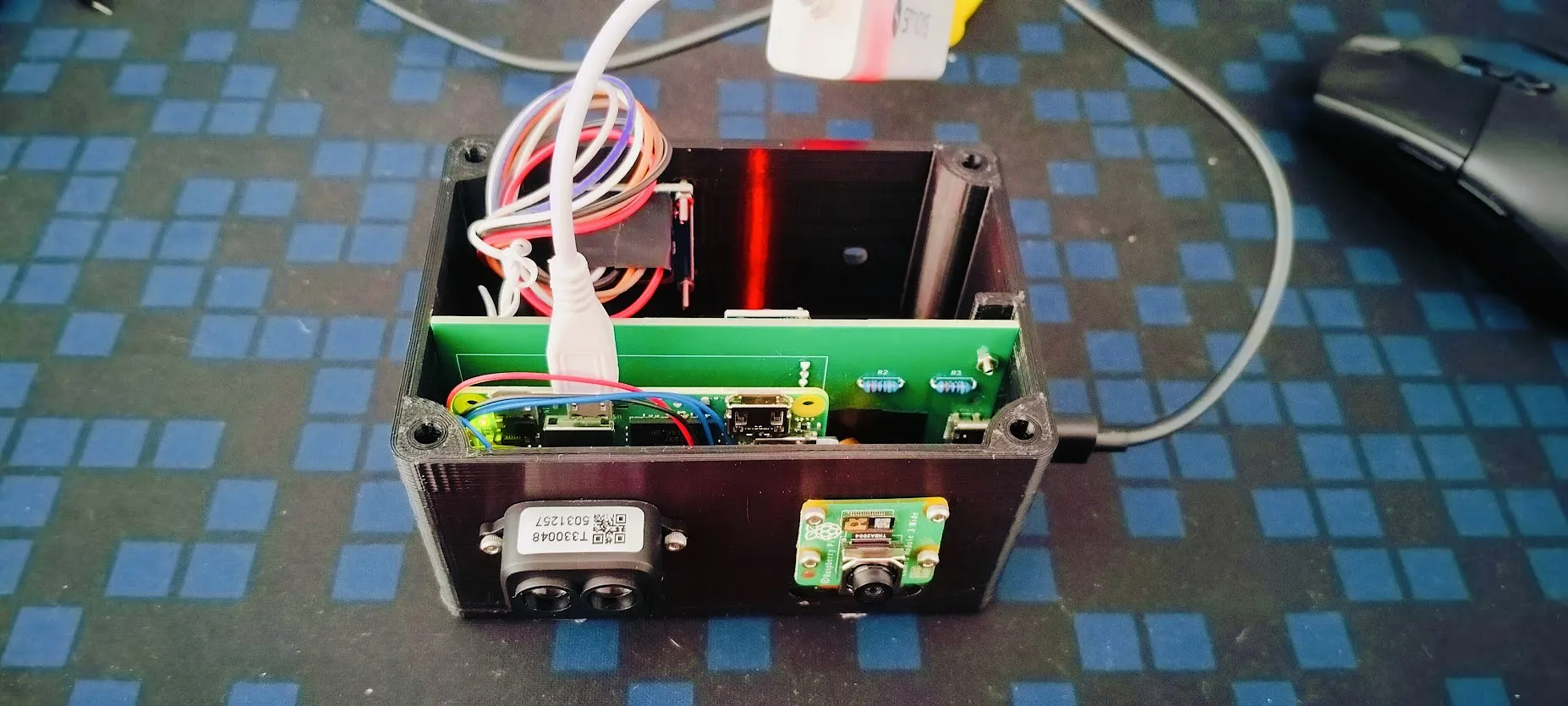
I decided to assemble the system inside the case because I knew the sensors were working. I did this by slotting the PCB into the case, then screwing the TF-Luna, camera, and OLED into their positions. I also installed the heat-set insert into the cutout at the bottom of the case. Everything fit correctly and lined up exactly as intended.
Lastly, I worked on the code with the help of Claude Code. We adapted the Arduino speed-detection logic to Python and added a 12-second calibration process that tested which of the gyroscope’s axes corresponded to the device’s horizontal rotation. This resulted in the first working speed-detection program running on the Pi.
I took it outside with my laptop and began testing. At first, the results were not accurate, and after some testing that led to no improvement, I developed a method to improve the code by having my dad drive past the sensor at roughly 20 km/h in sets of 10 passes, saving the sensor data after each run. I then used Claude Code to analyze the results, identify what was going wrong, and tune the parameters until the results improved.
The method clearly worked, because by the third round the system had gone from reporting impossible speeds to producing realistic and repeatable results. Most of the speed measurements had an error margin of around 5 km/h, which was far better than I had expected when starting the project.
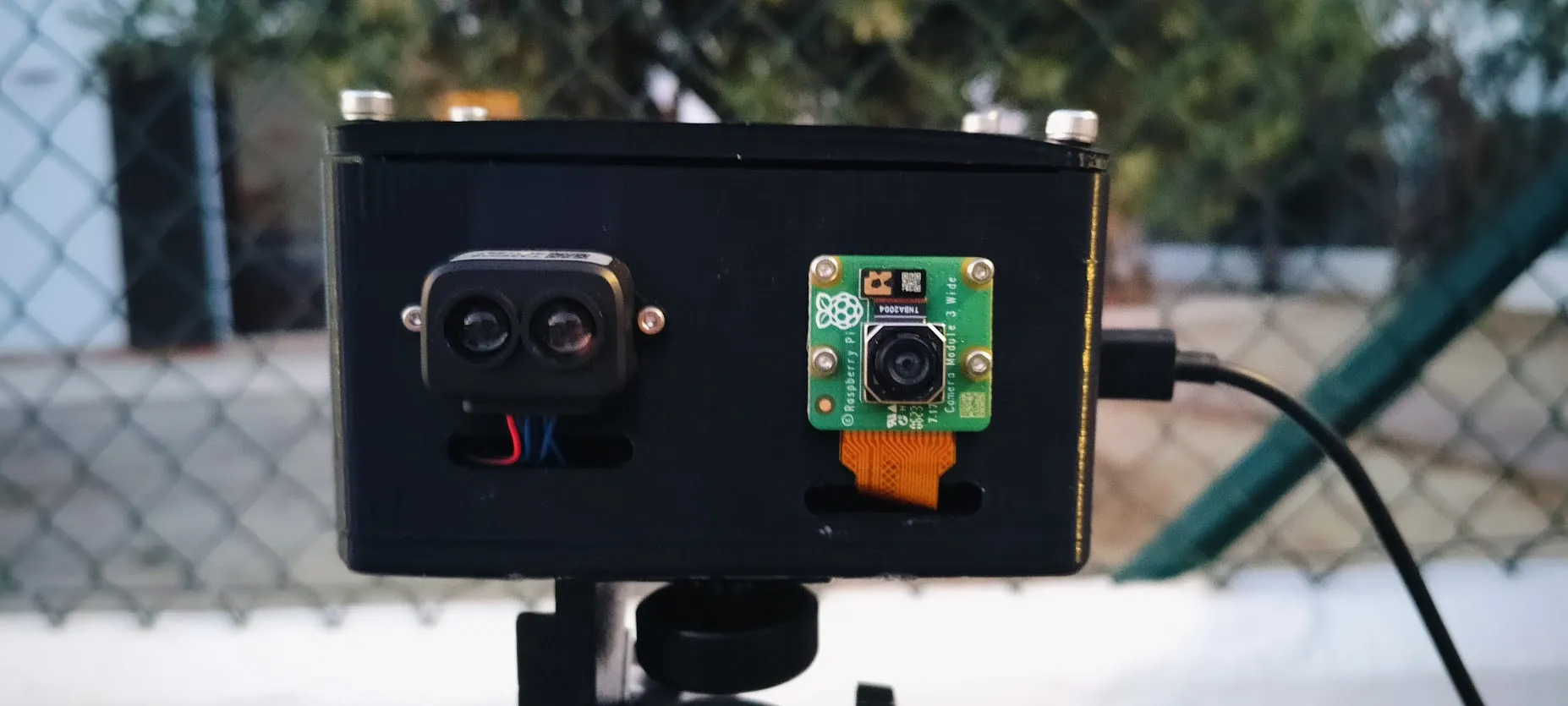
I finished the project by turning it into a completely standalone system with a dashboard that shows the image, speed, tilt, fit error, confidence, and other information for each capture. I also made the speed-detection code and dashboard start running as soon as the Pi powers on and attached a small power bank to the cover.
Odin’s Eye Demo:
I recommend having a look at the Blueprint page for Odin’s Eye because it gives a much more detailed account of the entire development process, including the setbacks, testing, design decisions, and improvements that led to the final project.
Odin’s Eye Blueprint: Odin’s Eye Blueprint
Odin’s Eye has been an incredible learning experience for me, going from barely knowing what hardware design was to designing, ordering, and soldering a fully functional PCB. This project took me through both the highs and the lows, but ultimately, I think that is what made it so rewarding. Seeing a project that started as a rough idea turn into a fully standalone speed camera capable of producing realistic results is something I am incredibly proud of. I plan on continuing to build even more ambitious hardware and software projects in the future.